Problem:
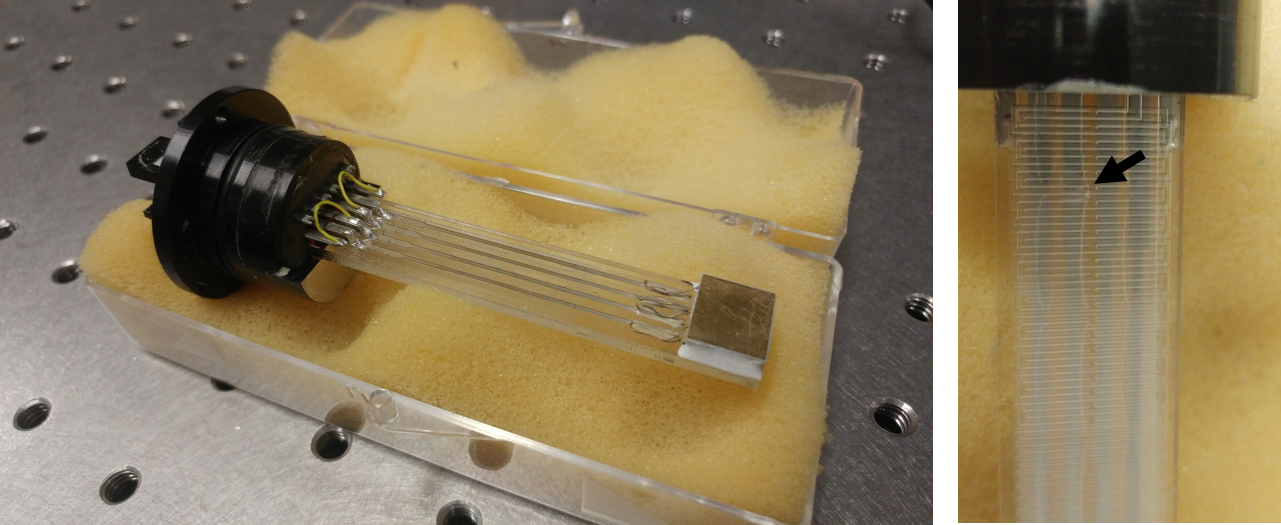
Prior to my arrival at Virginia Tech our group acquired an MMR Technologies cryogenic probe station capable of 8 probes. The sample stage is about 1cm2 and is cooled using high-pressure dry nitrogen through capillaries etched into glass or sapphire. High-pressure nitrogen flows through the capillaries where most of the pressure is dropped under the copper sample stage and then flows through a different path out of the vacuum chamber. This process is known as the Joule-Thomson effect and can cool the sample down to liquid nitrogen temperatures (77K) as long as everything works properly. The glass (or sapphire) stage is fragile and we were looking at ~$5K to replace one that got a short between the input and output capillaries rendering it useless. In the first picture below you can see the MMR Stage capable of 77K temperature and below it is a picture of the backside showing the capillaries and an arrow where the suspected ‘short’ is. I had been looking into finding a cryogenic probe station capable of helium temperatures <10K but those were even more expensive so instead I decided to integrate a CTI Cryodyne M22 cryopump into our MMR probe station.
Solution:
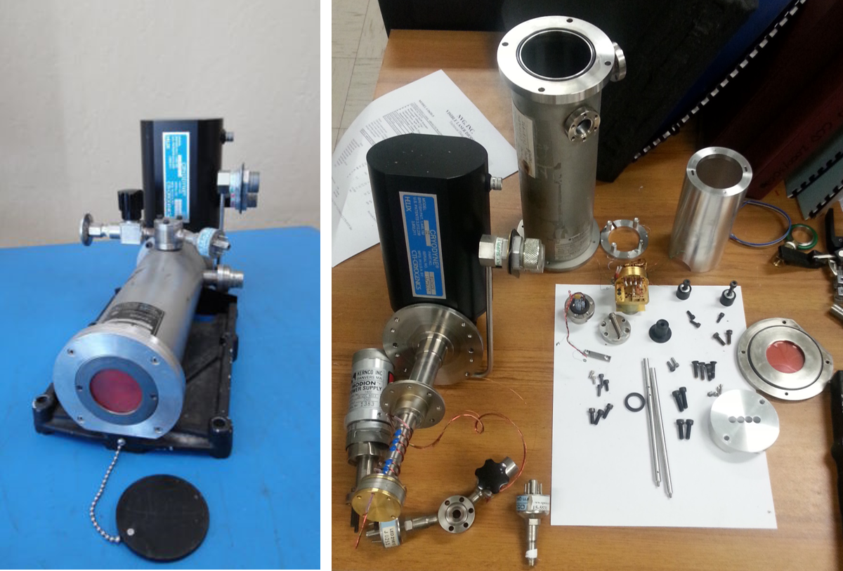
The cheapest option to cool something down in a vacuum seemed to be getting a hold of an eBay cryo pump but even those seemed to go for >$1000 for a working one. So after doing some digging I found a used Laser Photonics LM5731 originally used to test solid state IR lasers at cryogenic temperatures using an old CTI M22 pump (now Cryo Torr 100). The pictures below show the before and after disassembly showing all of the parts, most of which I was able to salvage and use like the vacuum cylinder shown in the top left of the ‘after’ picture.
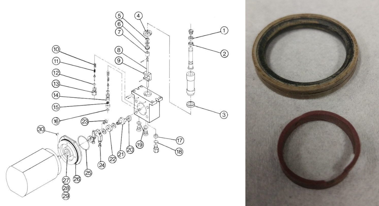
Imagine my disappointment when I realized that the pump worked but could only cool down to 120K and because I was self funding, I couldn’t just send it in to be diagnosed and repaired. So I did what any good engineer does and research common problems and made some calls. It turns out that these pumps are very similar to a Stirling engine and to work properly the working gas needs to be confined to the correct chamber using special seals namely the ‘expander ring’ and the ‘displacer seal’. Luckily I was able to find a company willing to sell me these parts for around $200 and the pump was able to get down to <30K! Below is the exploded view of the pump I had to beg for and next to it are the two seals, you can see how dirty they are and the fact that the Teflon on the top one is worn down in the middle.
Now that I was able to get down in temperature, I needed to find a way to mount the vacuum housing to the MMR probe station. Luckily, the designers of the MMR vacuum chamber thought to add a port on the bottom of the station (even if it was for a tubo upgrade) so I could connect straight to that. However, I needed to measure all of the cryo chamber dimensions and machine a coupling. Because I wanted to make sure to not ruin any of the expensive parts, I designed the coupling, and later the copper stage, so that no permanent holes or machining had to be done to the MMR chamber or the cryo pump components. Thus the most over-machined vacuum coupling was born.
By some miracle on the first try, I was able to pump the system down to same absolute pressure as when the chamber didn’t have a cryopump hanging off of it. So, the next step was to find some way to cool a sample down in the chamber using the 2nd stage of the cryopump. It might not be readily apparent but the tip of the pump sits about 6 inches below the point where the probes can contact a sample so I first needed to extend the length of the cold surface with a piece of oxygen-free copper. Next I wanted the ability to heat the sample stage without dropping too much of that heat into the cryo pump so I added 3 stainless steel standoffs as a thermal resistance. Finally, I added the sample stage with a couple holes designed to accept a 50W heater and a Pt thermometer. Again to my surprise, it worked the first time and I could successfully cool a sample down to ~50K! So I’m done right?… right?
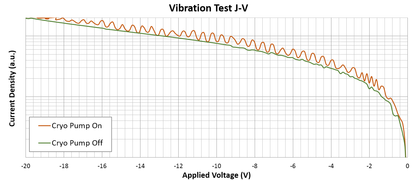
No, it turns out I didn’t plan for the small, in axis, vibration from the cryo pump displacers which caused <5μm sample movement. The vibration was enough to induce small periodic noise in the reverse IV characteristics of a schottky diode. I thought about trying to fix it by synchronizing the measurement instrument with the vibration but realized I needed to ultimately redesign the sample stage and anchor it to the vacuum chamber instead of the cryo pump. So back to the drawing board.
It took me awhile of thinking how I was going to do this because I now had to worry about how I was going to physically anchor the sample stage to the vacuum chamber but thermally isolate it so I wasn’t cooling down the whole apparatus. This problem was made harder by the fact I would lose cooling power from having to use a copper braid instead of a more solid stainless steel standoff like the previous sample stage. Thus, I settled on the design below, where I would break the sample stage into two pieces which would sandwich together on a disk with wave springs thereby taking care of most of the thermal isolation. The disk would then be anchored to the vacuum side of the machined coupling I mentioned previously with stainless steel standoffs. After some testing it worked! I was successfully able to cool the sample down to <50K without any noticeable current perturbations down to 1fA and have been taking measurements on it like a mad man. Check out the assembly of the stage below.