
Problem:
Ideally, to complement the DLTS system that our group owns we should also be able to excite electronic defects through and optical method to help understand the full extent of bandgap traps in GaN. A simple method known as Steady-State Photocapacitance measurements uses sudden exposures of single wavelength light to excite trapped charges out of deep states in a semiconductor and measures the response with a fast capacitance meter. In other words we put a shutter between a sample and the light source, let the sample sit in the dark for some time and then open the shutter and see what happens.
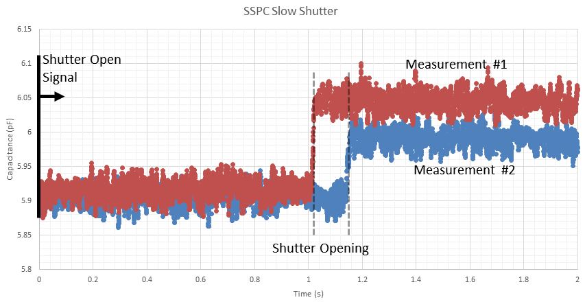
The problem I was facing was trying to time the exposure of light accurately with a safety shutter (Oriel 71445) and a digital signal from a LabVIEW program. Results can be seen below where I send the signal to open the shutter but the delay to open isn’t consistent which makes automation of detailed analysis almost impossible.
Solution:
The first idea was to buy something since “a simple shutter shouldn’t be expensive” but after looking I found that was not the case. The next idea (like most of mine are) was to try and make one. Since there didn’t seem to be ‘broken’ shutters on eBay I looked to try and score repair parts for a DSLR camera and reverse engineer the pins. Below is a picture of the D750 Shutter Blade Assembly Replacement I bought.
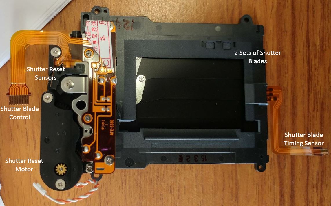
It took a little while to figure out how the shutter worked and in turn how to control it but it goes something like this. The light blocking method is accomplished with two shades which are tensioned with a spring. The motor will cock both of the shades until the metal core connector piece (connected to the shade) touches the electromagnet core. If power is running through the inductor, when the metal piece touches the core it will stick, thereby keeping the shade anchored. Once power to the inductor is stopped the spring tension pulls the shade back to the original position.

The final piece of the puzzle is the motor position. When the motor cocks the shutter blades it needs to keep moving so that the cocking arm isn’t in the way when the shades are ultimately relaxed to their original position. This is difficult because the shutter assembly uses a DC motor and has no feedback. This was solved by putting a few notches into one of the motor gears and sensing the notches with a couple photointerrupters. This is what is implemented on the D750 shutter assembly.

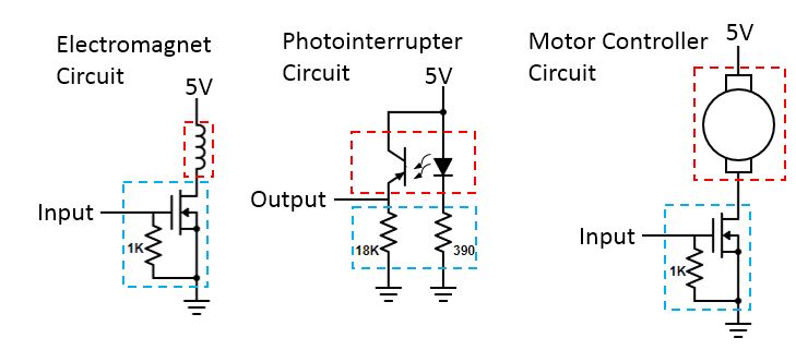
Now that we generally understand how the shutter works we need to setup a circuit and microcontroller to cock the shutter blades and then release them when ready. I decided to that the following circuits would be adequate to control the electromagnets and motor and then sense the position of the motor. The red outline indicates the circuit exists on the shutter assembly and the blue represents a circuit I need to implement.
With some probing around to discover the polarity of some of the circuits, below is the full interface diagram I implemented to control the shutter assembly. Notice that I’ve also added a voltage buffer (op-amp) for the input. I’m connecting a digital signal from the LabVIEW DAC over a long BNC cable and found that when connecting it directly to the gate of the MOSFET the voltage sagged (probably because of the 1K pull-down resistor) so I decided to add the opamp in series to increase the input impedance.

The code I used is below. Basically, the BNC input in the circuit above controls whether or not the OPEN electromagnet is holding the shutter blade and the Arduino is just checking whether or not the digital signal is high or low. After the BNC input indicates that it’s ready for the shutter to be reset the Arduino sends a full power PWM signal to the motor control MOSFET until its reset the shutter blades at which point it will cut the power down to 10% (duty cycle 20 of 255). Then it will wait until the motor position is at the correct point to turn the motor off. I found that if the program turned the motor off from 100%, the momentum would push it past the correct reset position and the blades would get stuck. Lowering the power while it was still moving gave it enought of a push to make it around again but not enough to cause the motor to drift when it was turned off.
1
2
3
4
5
6
7
8
9
10
11
12
13
14
15
16
17
18
19
20
21
22
23
24
25
26
27
28
29
30
31
32
33
34
35
36
37
38
39
40
41
42
43
44
45
46
47
48
49
50
51
52
53
54
55
56
57
58
59
60
61
62
63
64
65
66
67
68
69
70
71
72
73
74
unsigned long time;
void setup() {
pinMode(2,INPUT); //Open Shutter Hold
pinMode(3,OUTPUT); //Close Shutter Hold
pinMode(6,OUTPUT); //Motor
pinMode(13,OUTPUT); //Debug LED
pinMode(7,INPUT); //Motor PhotoInterrupter 1
pinMode(5,INPUT); //Motor PhotoInterrupter 2
}
void loop() {
// put your main code here, to run repeatedly:
while(digitalRead(2)){ //Wait until High-Low
__asm__("nop\n\t");
}
digitalWrite(13,false); //Turn LED OFF
delay(5); //Wait for Bounce
while(!digitalRead(2)){ //Wait until Low-High
__asm__("nop\n\t");
}
delay(5); //Wait for bounce
if(digitalRead(2)){ //Check actually high
digitalWrite(3,false); //Close Shutter
delay(150); //Wait for close
digitalWrite(13,true); //Turn LED ON
digitalWrite(3,true); //Engage Close Shutter Hold
ResetMotor();
}
}
void ResetMotor(){
analogWrite(6,255);//Turn motor on to reset
time = millis();
while(!(digitalRead(7) == HIGH && digitalRead(5) == HIGH)){ //Wait until motor out of correct position
if((millis()-time)>500){analogWrite(6,0);return;}
}
time = millis();
while((digitalRead(7) == HIGH && digitalRead(5) == HIGH)){ //Wait until motor out of correct position
if((millis()-time)>500){analogWrite(6,0);return;}
}
analogWrite(6,20);//Turn motor on to reset
time = millis();
while(!(digitalRead(7) == HIGH && digitalRead(5) == HIGH)){ //Wait until motor out of correct position
if((millis()-time)>500){analogWrite(6,0);return;}
}
time = millis();
while((digitalRead(7) == HIGH && digitalRead(5) == HIGH)){ //Wait until motor out of correct position
if((millis()-time)>500){analogWrite(6,0);return;}
}
time = millis();
while(!(digitalRead(7) == LOW && digitalRead(5) == LOW)){ //Wait until motor in correct position
if((millis()-time)>500){analogWrite(6,0);return;}
}
analogWrite(6,0); //Turn motor off
}